
 ENG
ENG
 English
 русский
 Français
 Español
OEM.NO: 0280 218 429 0280 218 430
See Details
REQUEST A QUOTE
How Does Airflow Meter Sensor Measure Air Intake In Engines
Why Does Airflow Measurement Matter In Engine Air Intake Systems?
Air going into an engine carries more meaning than it seems. It is part of how the engine keeps its rhythm while working under different loads and speeds. When intake air shifts, engine behavior also shifts in a quiet way. Sometimes the change is small, sometimes more noticeable during acceleration or idle movement. Because of that, airflow measurement becomes part of the intake system rather than an added feature.
An Airflow Meter Sensor sits in the intake path and watches how air moves through it. The reading is not a one-time check. It keeps changing as long as the engine is running. Intake air never stays still, so the sensor keeps updating its output to match the movement.
Air entering the system is shaped by many small conditions. Throttle position, filter resistance, duct layout, and outside air changes all affect how it flows. Without a sensor, those changes stay invisible. With measurement in place, airflow becomes a signal the system can use.
Common reasons airflow measurement is needed:
- intake air shifts with driving condition
- engine response depends on air balance
- airflow changes during load variation
- intake path behavior is never constant
- system adjustment needs live airflow feedback
Instead of giving a fixed number, the sensor follows airflow as it changes. That steady tracking is what keeps the intake system responsive.
How Does An Airflow Meter Sensor Work In Measuring Intake Air?
Inside the intake duct, air keeps moving toward the engine. The Airflow Meter Sensor is placed along this path where air passes through a controlled section. When air moves through, it interacts with a sensing element inside the device.
That interaction creates a physical change. Depending on the design, it may involve heat transfer or a change in electrical resistance. The sensor reads that change and turns it into a signal.
The signal does not stay still. It rises and falls as airflow increases or decreases. That signal is then sent to the control system, which adjusts intake behavior based on what it receives.
A simple flow looks like:
- air enters intake channel
- air passes sensing area
- sensing element reacts to movement
- physical change becomes signal
- signal moves to control unit
- intake response adjusts to airflow
The sensor works continuously because air keeps moving continuously. Even small shifts in airflow speed or density appear in the signal output.
It also does not work alone. Air passes through filters, bends in ducts, and pressure changes before reaching the sensor. All of that becomes part of the reading.
What Physical Principles Support Airflow Detection Inside Sensors?
Airflow sensing depends on how moving air interacts with something physical inside the sensor. One common idea is heat exchange. A small heated element sits in the airflow path. As air moves across it, heat is carried away.
When airflow is stronger, more heat is removed. When airflow is weaker, less heat is removed. That difference becomes a signal.
Another method comes from changes in electrical behavior. Air moving across a sensing surface slightly changes how that material behaves electrically. That small shift is also used as airflow information.
Both methods follow the same logic: air moves, something changes, and that change becomes a signal.
Key behaviors involved:
- heat transfer between air and sensing surface
- change in resistance during airflow movement
- short delay during sudden airflow shifts
- steady behavior during constant intake flow
Air inside the intake system is rarely smooth. It can carry turbulence, pressure changes, and temperature variation. The sensor has to respond without losing track of those changes.
How Does Airflow Meter Sensor Integrate Into Engine Air Intake Pathways?
The Airflow Meter Sensor is not placed randomly inside the intake system. It sits in a section where airflow can be measured before air reaches the combustion area.
Air usually enters through a filter section first. After that, it moves through ducts toward the engine. The sensor is installed in a point where airflow still represents real intake conditions.
Once installed, the sensor becomes part of a simple loop. Air passes through, the sensor reads it, and a signal is sent to the control system. The system then adjusts intake behavior based on that signal.
The path can be seen like this:
- air enters intake system
- air moves through duct section
- airflow passes sensor position
- signal is generated
- signal is sent to controller
- intake adjustment follows airflow change
This position matters because it allows airflow to be measured before it fully enters the engine cycle.
Why Is Signal Stability Important In Airflow Monitoring Systems?
Airflow inside an engine intake system is never steady. It changes with every movement of the throttle, every load shift, and every change in engine speed. The sensor has to turn those changes into a signal that stays readable.
If the signal becomes unstable, the control system may react to uneven information.
During quick changes in engine operation, airflow can shift within a short moment. The signal needs to follow those shifts without delay or distortion.
Things that affect signal stability:
- turbulence inside intake duct
- fast changes in airflow speed
- pressure variation in intake path
- response speed of sensing element
A steady signal helps the intake system react in a smoother way instead of overreacting to short airflow changes.
How Do Environmental Conditions Influence Airflow Sensor Performance?
Air entering the intake system is already shaped by outside conditions before it reaches the sensor. Temperature, dust, and moisture all play a role in how air behaves.
Temperature changes affect air density. That changes how air moves through the intake path and how the sensor reads it.
Dust particles can pass through the system even with filters in place. Over time, small buildup may affect how smoothly air flows across the sensing area.
Moisture in the air also changes flow behavior. Humid air does not move exactly the same way as dry air, which can influence readings in subtle ways.
Environmental influences include:
- temperature changes affecting air density
- dust presence in intake flow
- moisture variation in air
- shifting outside conditions during operation
The sensor keeps working under all these conditions, adjusting output based on actual airflow movement inside the system.
How Does An Airflow Meter Sensor Link With Engine Control Response?
Air moving through an intake system never settles into one fixed pattern. It keeps changing with throttle action, road load, and small pressure shifts inside the duct. An Airflow Meter Sensor follows those changes and turns them into an electrical signal that travels into the engine control system.
After that point, the signal becomes part of intake adjustment. Nothing stays separate for long. Air changes, sensor reacts, control system responds, and then air movement changes again.
The whole process feels more like a loop than a single measurement:
- air enters intake path
- sensor picks up movement
- signal forms from airflow change
- control system receives signal
- intake adjustment takes place
- airflow shifts again
Even when the change is small, it still passes through the same cycle.
Why Do Driving Conditions Change Sensor Behavior?
Airflow inside an engine does not stay consistent. It depends on how the engine is being used at that moment. Light load, steady movement, and sudden throttle changes all create different air movement inside the duct.
At steady movement, air passes through the intake in a smoother way. The signal from the sensor tends to stay more even. During sudden throttle changes, air moves in a more uneven pattern for a short time, and the sensor reflects that shift right away.
Nothing inside the sensor changes. What changes is the air passing through it. That is enough to create different signal patterns.
What Role Does Air Flow Sensor Manufacturer Have In Sensor Design?
An air flow sensor manufacturer focuses less on appearance and more on how air behaves inside real intake systems. Air is not clean and steady all the time. It carries small turbulence, pressure shifts, and temperature variation.
Because of that, design choices usually aim to keep the signal from becoming too unstable when air conditions shift.
Key design focus areas include:
- reaction to fast airflow changes
- behavior during steady airflow
- tolerance to intake turbulence
- long-term signal consistency
- stability under mixed air conditions
Small changes in internal structure can affect how airflow turns into signal output, especially when conditions are not stable.
How Does Sensor Placement Change Airflow Reading?
Position inside the intake duct has a direct effect on what the sensor sees. Air does not move the same way in every section of the duct. Some areas are smooth, others are disturbed by bends or filter effects.
If the sensor sits in a disturbed zone, airflow looks less stable. If it sits in a smoother section, readings tend to look more steady.
Simple comparison:
| Sensor Position | Airflow Condition | Signal Behavior |
|---|---|---|
| Near turbulence zone | Uneven airflow | Fluctuating response |
| Straight duct section | smoother airflow | stable signal pattern |
| Near airflow bends | mixed airflow direction | irregular readings |
| Balanced flow area | controlled airflow | consistent output |
The airflow does not change because of the sensor. The reading changes because the air behaves differently in each location.
What Happens To Airflow Sensors Over Time?
An airflow sensor works inside a moving air path for a long period. Air is not pure. It carries small particles, moisture, and temperature changes. Over time, those conditions leave small marks on how the sensor responds.
One common effect is light buildup on sensing areas. It does not stop operation, though it can slightly change how air interacts with the surface.
Another effect is slow change in signal response. After long use, output may not feel exactly the same as when it was new. It still works, only the response becomes slightly different.
Repeated airflow changes also play a role. Rapid shifts in engine load push air through sudden movement cycles, and the sensor keeps reacting to each one.
Main long-term influences:
- small particle buildup on sensing surface
- slow shift in signal response behavior
- repeated exposure to airflow changes
- variation in intake air conditions
Even with those changes, the sensor continues working as part of the intake system without stopping its basic function.
How Are Airflow Meter Sensor Used In Different Engine Setups?
Airflow Meter Sensor appear in different engine systems, though the basic idea stays the same. Air enters, sensor reads movement, and signal goes into control adjustment.
In systems where engine load changes often, airflow shifts more frequently. The sensor follows those changes continuously.
In steadier systems, airflow remains smoother for longer periods. The sensor output also stays more stable.
In systems with mixed conditions, airflow can change quickly from one state to another. The sensor response follows those shifts as they happen.
Simple view of different usage conditions:
| Engine Environment | Airflow Behavior | Sensor Role |
|---|---|---|
| Passenger systems | frequent changes | continuous adjustment support |
| Industrial systems | steadier flow | long-cycle stability tracking |
| Variable load systems | rapid shifts | fast response tracking |
| Controlled systems | balanced flow | steady monitoring role |
Across all setups, the role stays the same. Airflow moves, sensor reads it, system adjusts based on what is happening in the intake path.
Related products
-
-
-
-
-
-
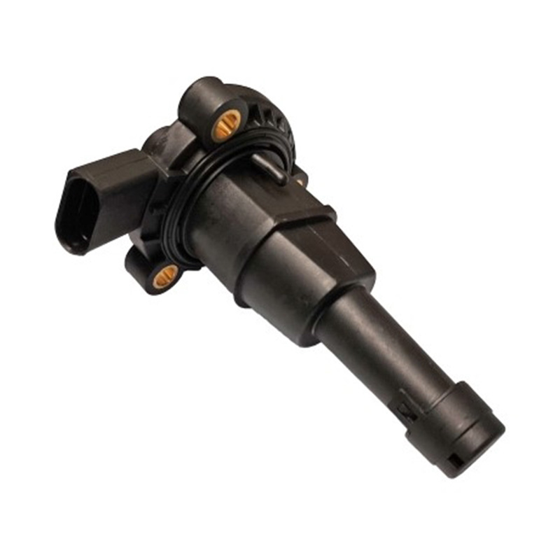
OEM.NO: 03F 907 660C. 03F 907 660D. 03F 907 660E95810360000
See Details

PRODUCTS
CONTACT INFO.
- +86-18057729678/+86-13587780979
- +86-577-62369668
- [email protected]
- No. 21 Xinda Road, xin'ao industrial zone, Hongqiao, Yueqing, Zhejiang, China
QR CODE
Copyright © Wenzhou Xinlianke Mold Industry Co., Ltd. All Rights Reserved.

Car Mass Air Flow Meter Manufacturer
 TOP
TOP